UTR2833E
300KHz
0.05%
6-bit
80rdgs/s
YES
RS232, HANDLER, USB HOST, USB DEVICE, LAN
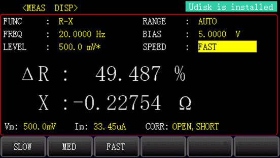
4.3'' TFT LCD
UTR2832E
200kHz
0.05%
6-bit
80rdgs/s
YES
RS232, HANDLER, USB HOST, USB DEVICE, LAN
4.3'' TFT LCD
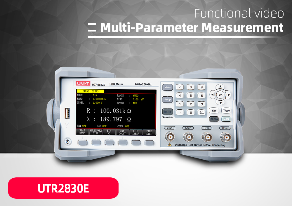
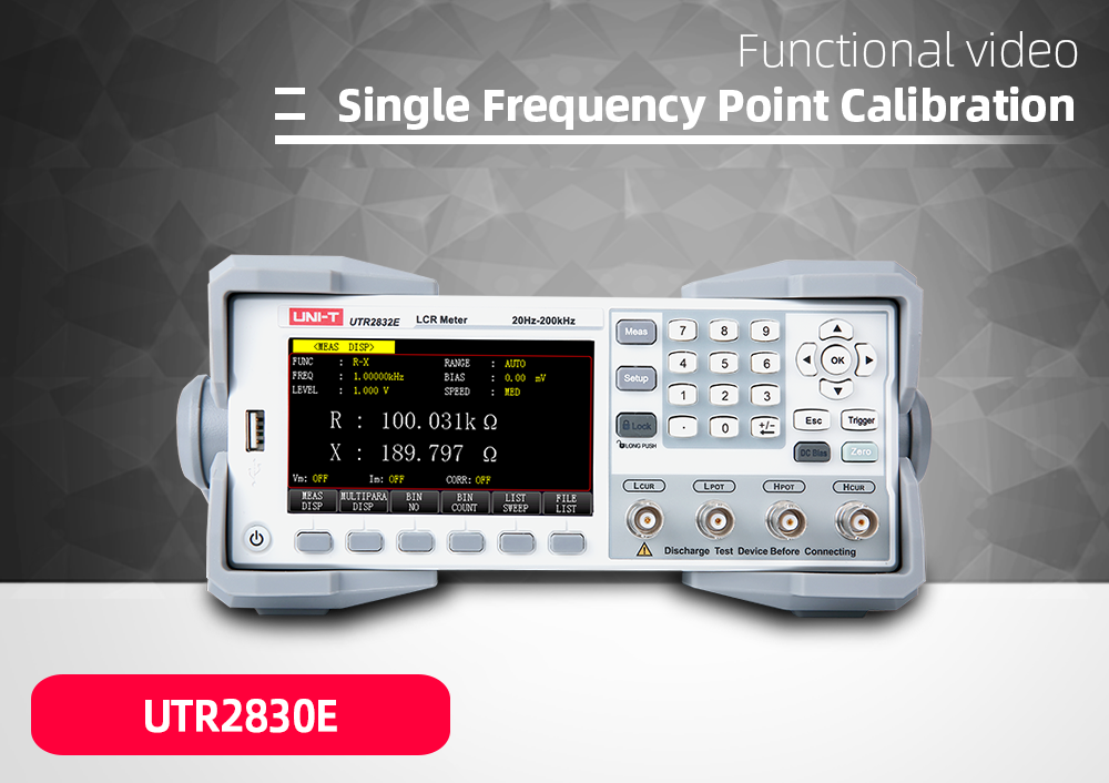
UTR2830E
100KHz
0.05%
6-bit
80rdgs/s
YES
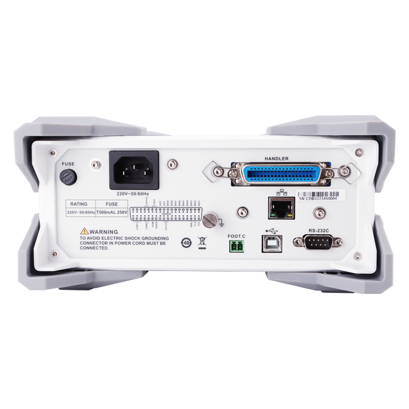
RS232, HANDLER, USB HOST, USB DEVICE, LAN
4.3'' TFT LCD
UTR2833E
MAX. TEST FREQUENCY:300KHz
ACCURACY:0.05%
DISPLAY COUNT:6-bit
MAX. TEST RATE:80rdgs/s
DCR:YES
CONNECTIVITY:RS232, HANDLER, USB HOST, USB DEVICE, LAN
DISPLAY:4.3'' TFT LCD
UTR2832E
MAX. TEST FREQUENCY:200kHz
ACCURACY:0.05%
DISPLAY COUNT:6-bit
MAX. TEST RATE:80rdgs/s
DCR:YES
CONNECTIVITY:RS232, HANDLER, USB HOST, USB DEVICE, LAN
DISPLAY:4.3'' TFT LCD
UTR2830E
MAX. TEST FREQUENCY:100KHz
ACCURACY:0.05%
DISPLAY COUNT:6-bit
MAX. TEST RATE:80rdgs/s
DCR:YES
CONNECTIVITY:RS232, HANDLER, USB HOST, USB DEVICE, LAN
DISPLAY:4.3'' TFT LCD


 UTR2830 Series LCR Meters - Data Sheet