Select a country or region to access content specific to your location.
Confirm
This website uses cookies to improve user experience. By using our website you consent to all cookies in accordance with our Cookie Policy.
>
>
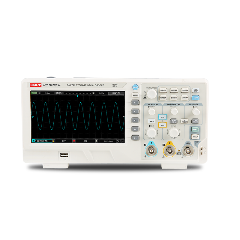
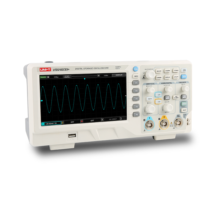
UTD2000CEX+ Series
UTD2000CEX+ Series
The UTD2000CEX+ provides a richer trigger mode, 34 kinds of automatic parameter measurement and common mathematical operation functions, and optimizes the panel operation, which greatly improves the work efficiency and can easily cope with the measurement needs of complex signals.
50MHz~200 MHz
BANDWIDTH
2
ANALOG CHANNELS
1 GSa/s
REAL-TIME SAMPLE RATE
64 kpts
MAX. MEMORY DEPTH
5,000 wfms/s
WAVEFORM CAPTURE RATE
/
DIGITAL CHANNELS
FEATURES
MODEL
MANUAL
OPTIONS&ACCESSORIES
SOFTWARE&FIRMWARE
VIDEO
FAQS
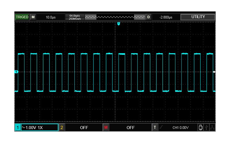
Wider display range and multiple frequency square wave options
The UTD2000CEX+ series display range is 8divX16div,
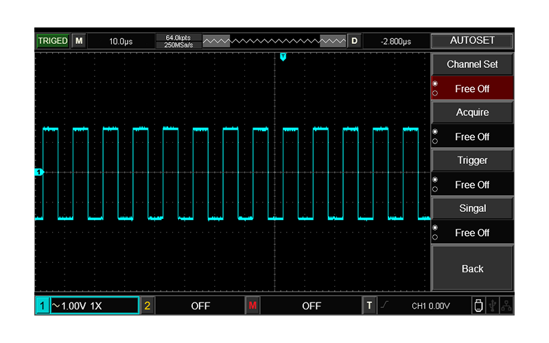
and has a new AUTOSET strategy, which can easily copewith complex test scenarios.
Wider display range and multiple frequency square wave options
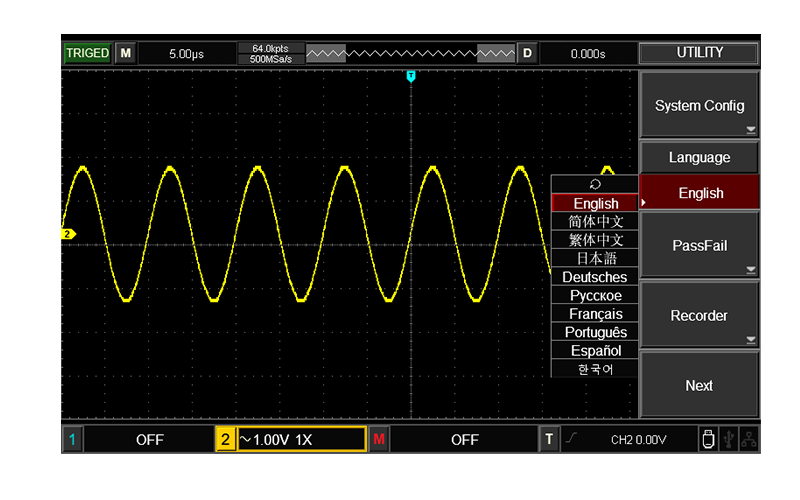
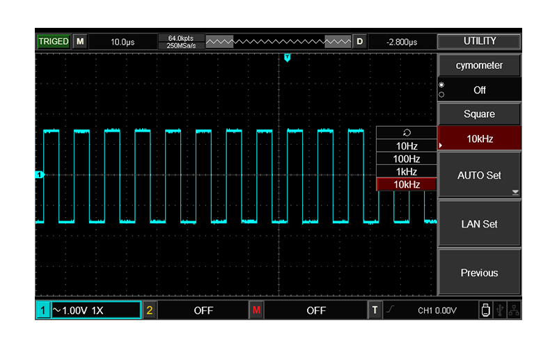
Multi-language optional, multi-frequency square wave optional
With 9 languages, it can meet the needs of users in more countries.
Output standard square wave 10Hz, 100Hz, 1kHz, 10kz optional.
Multi-language optional, multi-frequency square wave optional
Various parameter measurement and waveform recording functions
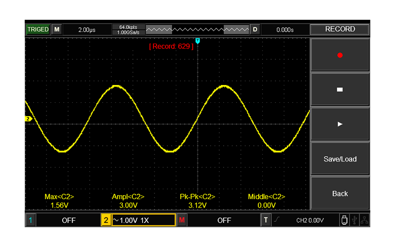
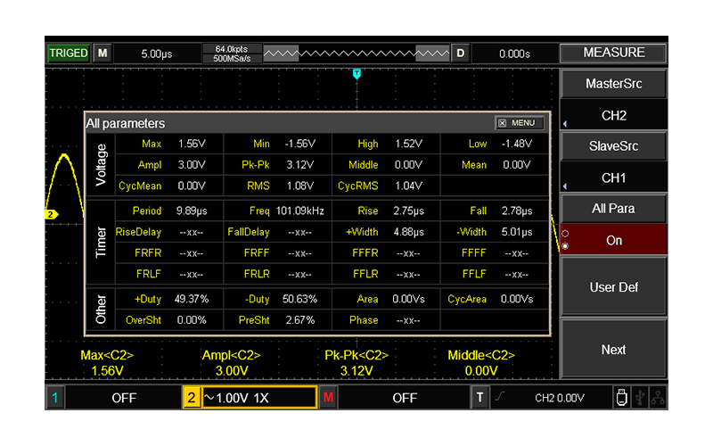
The UTD2000CEX+ series supports 34 kinds of automatic measurement functions and waveform recording functions, which can record up to 1000 frames, and can achieve better waveform analysis effects through playback and storage functions.
Various parameter measurement and waveform recording functions
MODEL
UTD2202CEX+
BANDWIDTH:200 MHz
ANALOG CHANNELS:2
REAL-TIME SAMPLE RATE:1 GSa/s
MAX. MEMORY DEPTH:64 kpts
WAVEFORM CAPTURE RATE: 5,000 wfms/s
DIGITAL CHANNELS:/
WAVEFORM GENERATOR:/
UTD2052CEX+
BANDWIDTH:50MHz
ANALOG CHANNELS:2
REAL-TIME SAMPLE RATE:1 GSa/s
MAX. MEMORY DEPTH:64kpts
WAVEFORM CAPTURE RATE:5,000 wfms/s
DIGITAL CHANNELS:/
WAVEFORM GENERATOR:/
UTD2102CEX+
BANDWIDTH:100 MHz
ANALOG CHANNELS:2
REAL-TIME SAMPLE RATE:1 GSa/s
MAX. MEMORY DEPTH:64 kpts
WAVEFORM CAPTURE RATE:5,000 wfms/s
DIGITAL CHANNELS:/
WAVEFORM GENERATOR:/
Data Sheet
download UTD2000CEX+ Series Digital Oscilloscopes - Data Sheet
Version:V1.0
Release Date:2024/8/6
QuickStart Guide
User Manual
download UTD2000 Series Digital Oscilloscopes - User Manual
Version:V1.0
Release Date:2024/8/7
download UTD2000 Series Digital Oscilloscopes - User Manual (Deutsch)
Version:V1.0
Release Date:2024/10/28
Programming Manual
download UTD2000CEX+ & UTD2000CL & UTD2000CL+Series Digital Oscilloscopes - Programming Manual
Version:V1.0
Release Date:2024/8/6
Service Manual
Performance Verification Guide
OPTIONS
ACCESSORIES
UT-P20
download EN
UT-P20
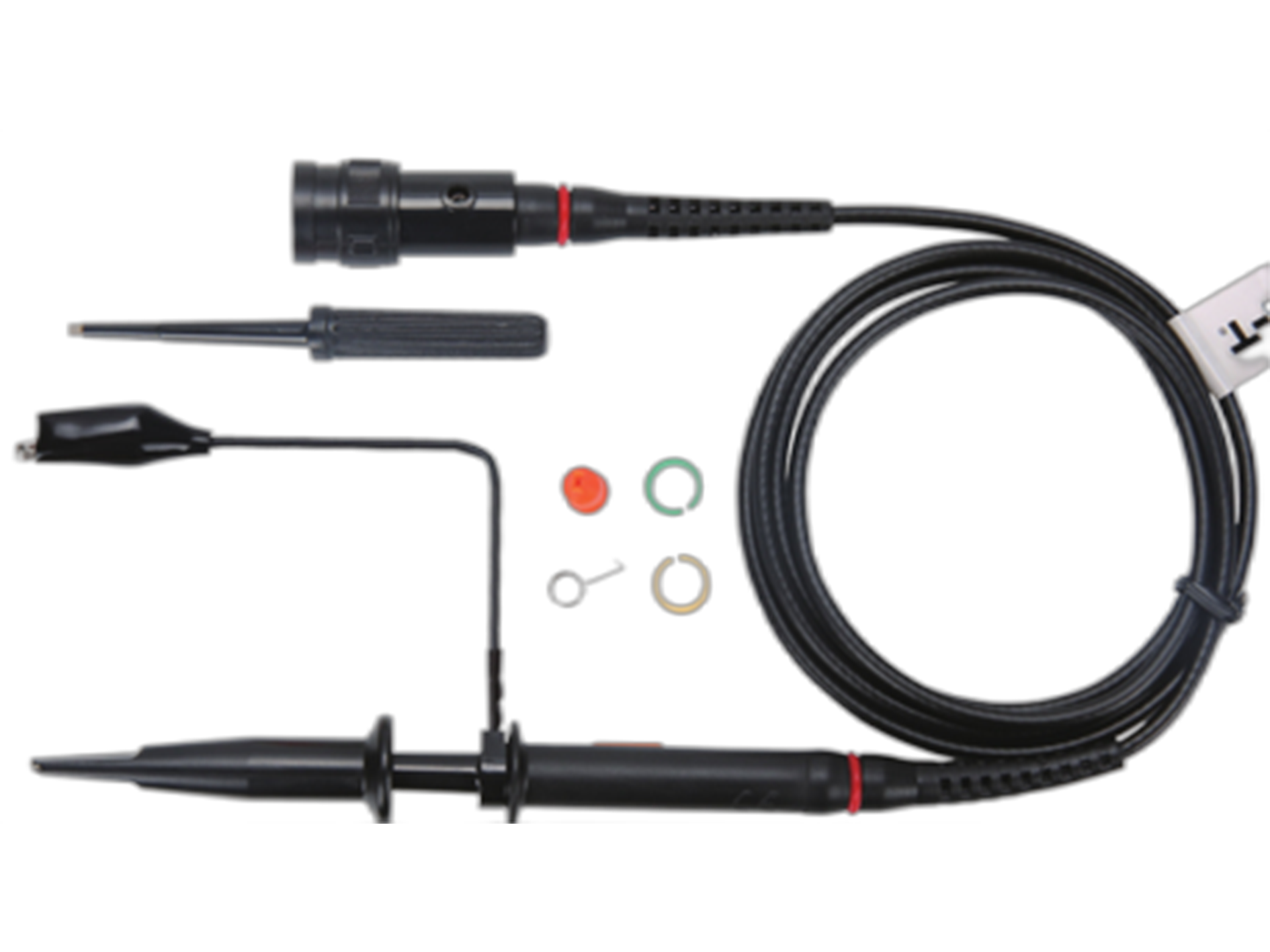
Description:Passive probe: (100:1) Bandwidth: 250MHz. voltage: 1500V
UT-P21
download EN
UT-P21
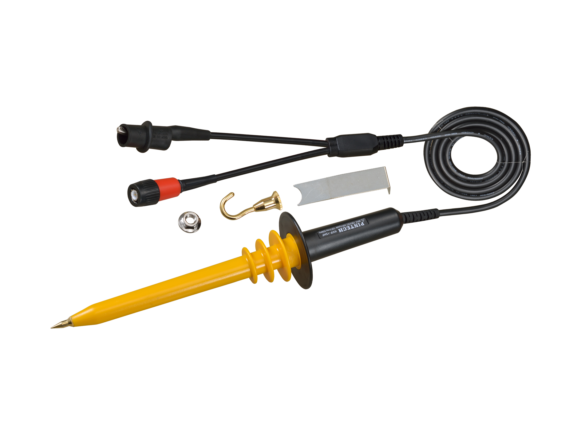
Description:Passive high voltage probe: (1000:1) Bandwidth: 40MHz voltage: DC 10kV/AC 7kVrms
UT-P30
download EN
UT-P30
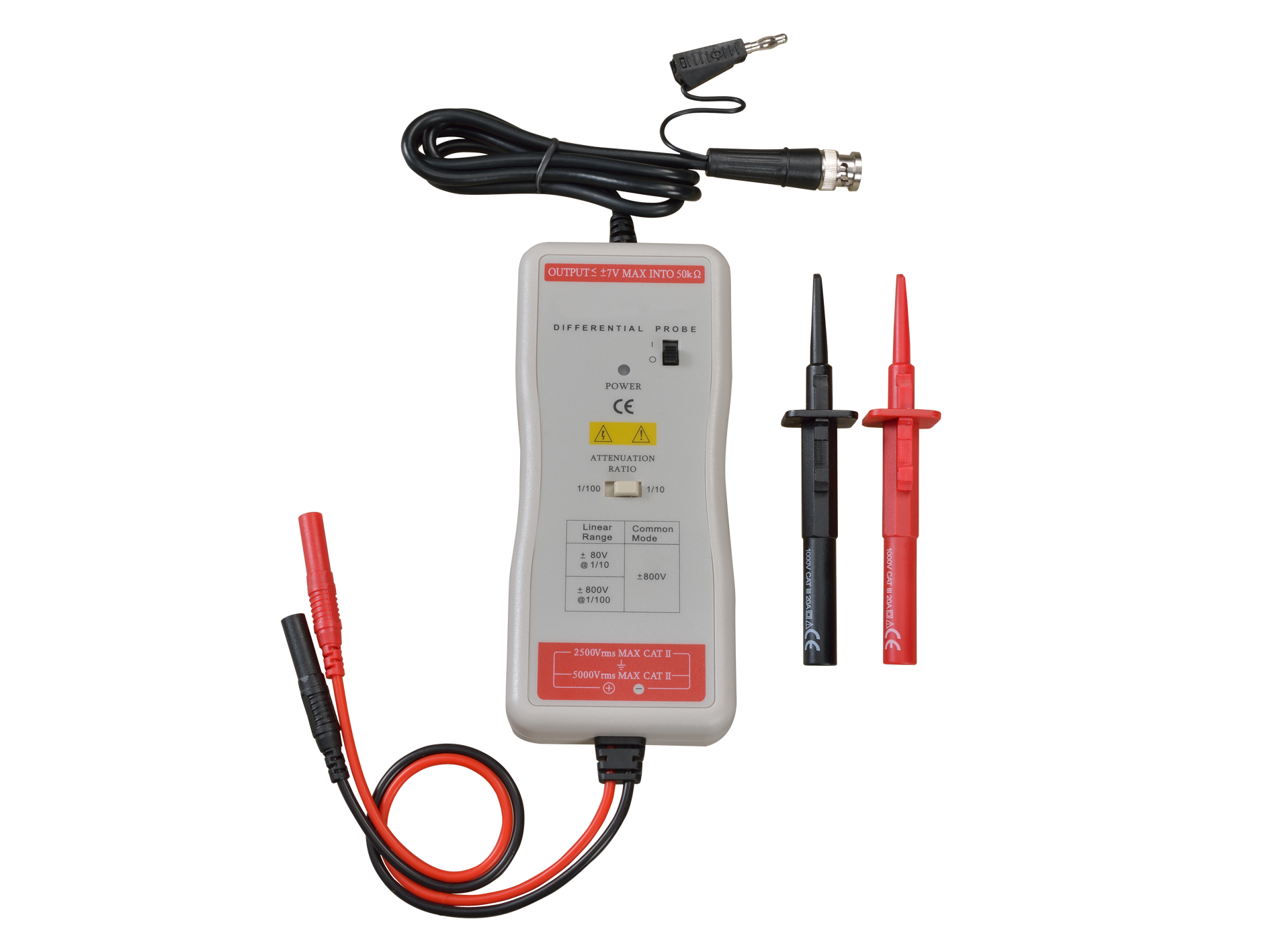
Description:Differential probe:(10:1/100:1) Bandwidth: 100MHz differential voltage: 800Vpp
UT-P31
download EN
UT-P31
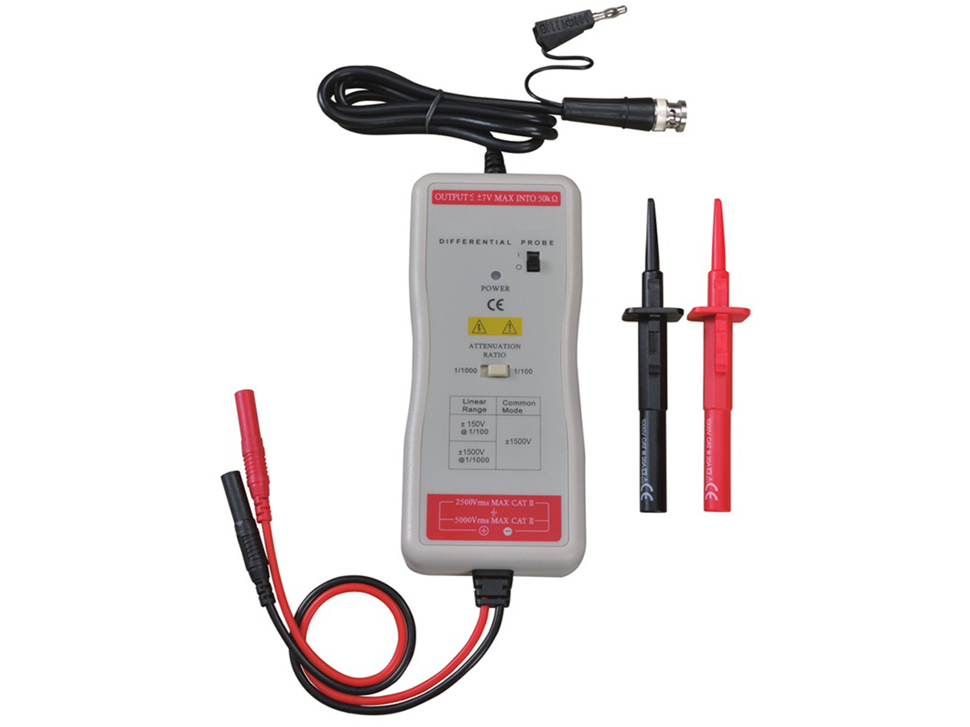
Description:High voltage differential probe: (100:1/1000:1) Bandwidth: 100MHz differential voltage: 1500Vpp
UT-P32
download EN
UT-P32
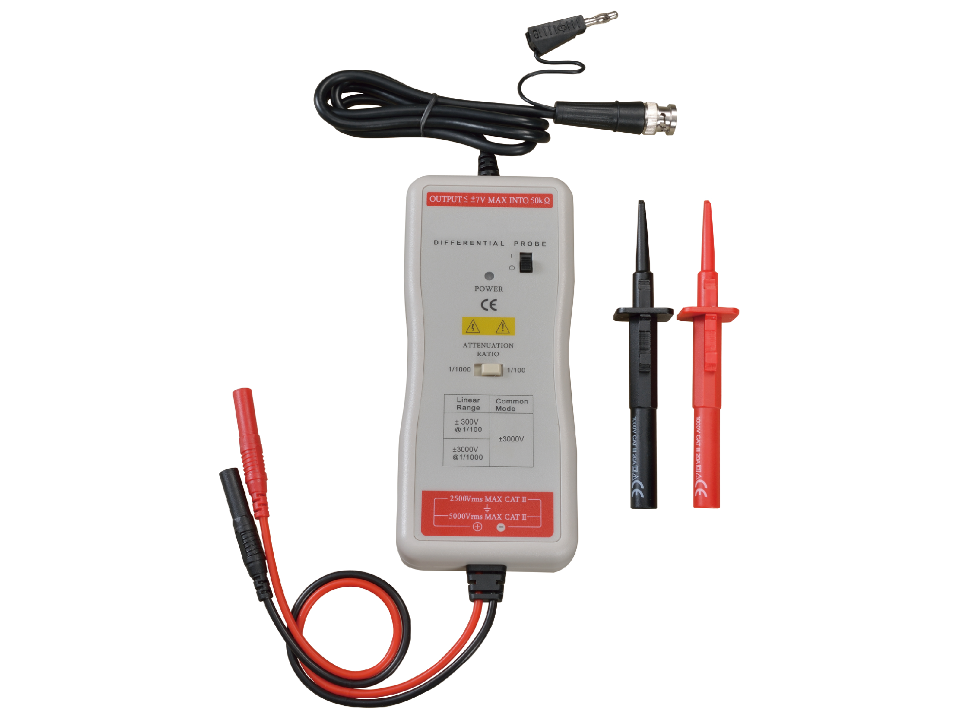
Description:Differential probe:(1000:1/100:1)Bandwidth: 50MHz Input differential voltage: 3000Vpp
UT-P33
download EN
UT-P33
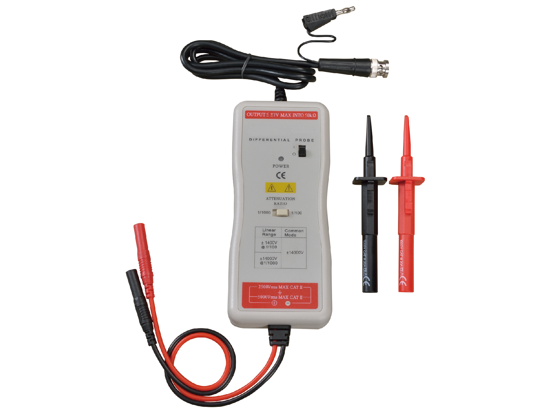
Description:Differential probe:(1000:1/100:1) Bandwidth: 70/50MHz differential voltage: 14KVpp
UT-V23
download EN
UT-V23
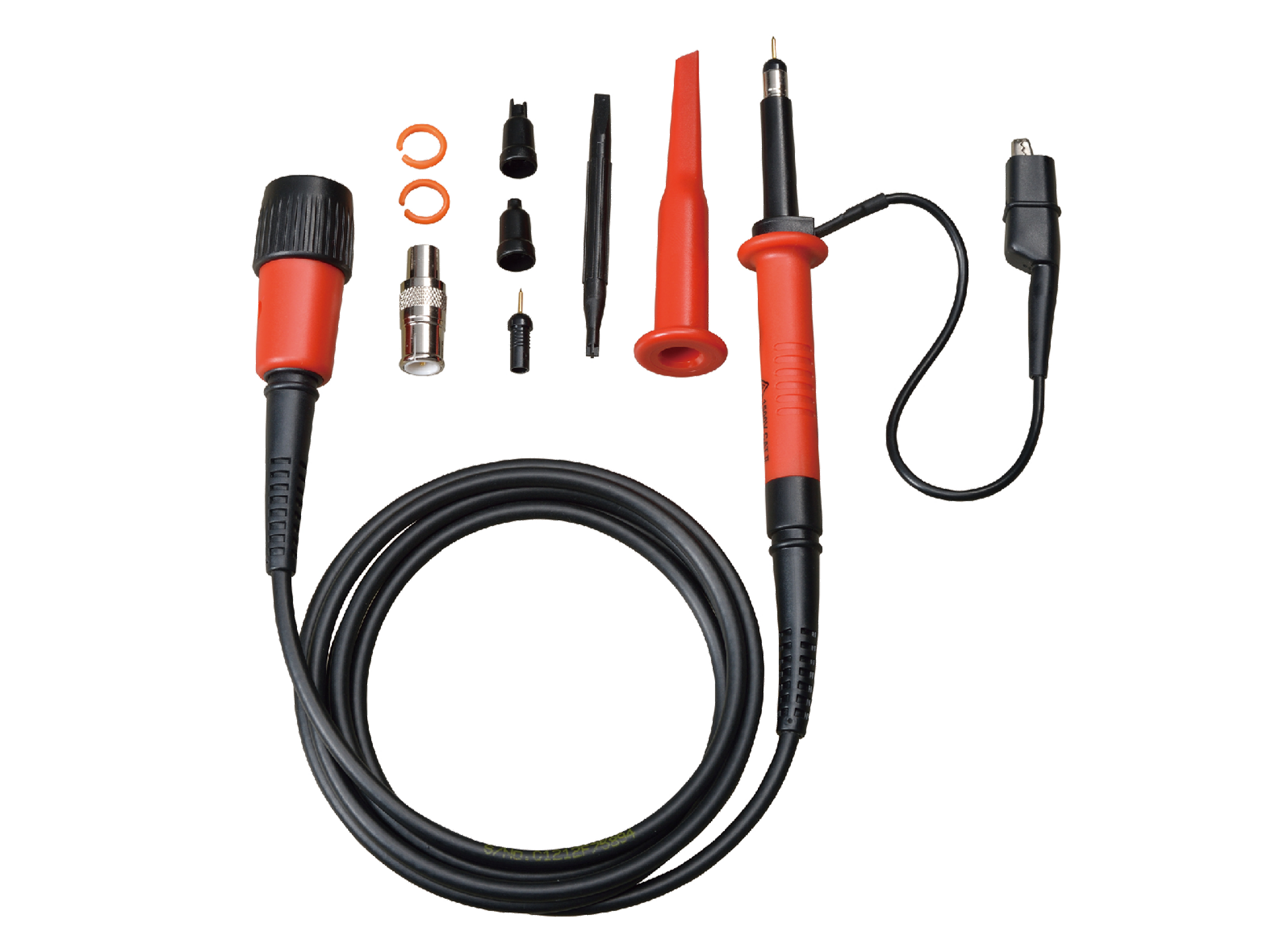
Description:High voltage probe:(100:1)Bandwidth: 100MHz voltage: 2000Vpp
UT-P40
download EN
UT-P40
Description:Conversion ratio:50mV/A, 5mV/A, Current range : 0.4A~60A,Frequency: DC~100kHz voltage: 600Vrms
UT-P41
download EN
UT-P41
Description:Conversion ratio:100mV/A, 10mV/A, Current range: 50mA~100A Frequency: DC~100kHz, voltage: 600Vrms
UT-P43
download EN
UT-P43
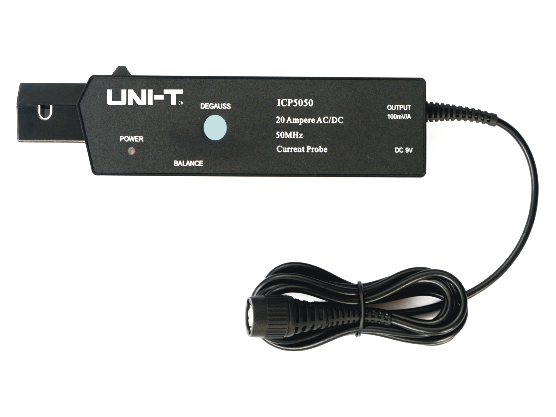
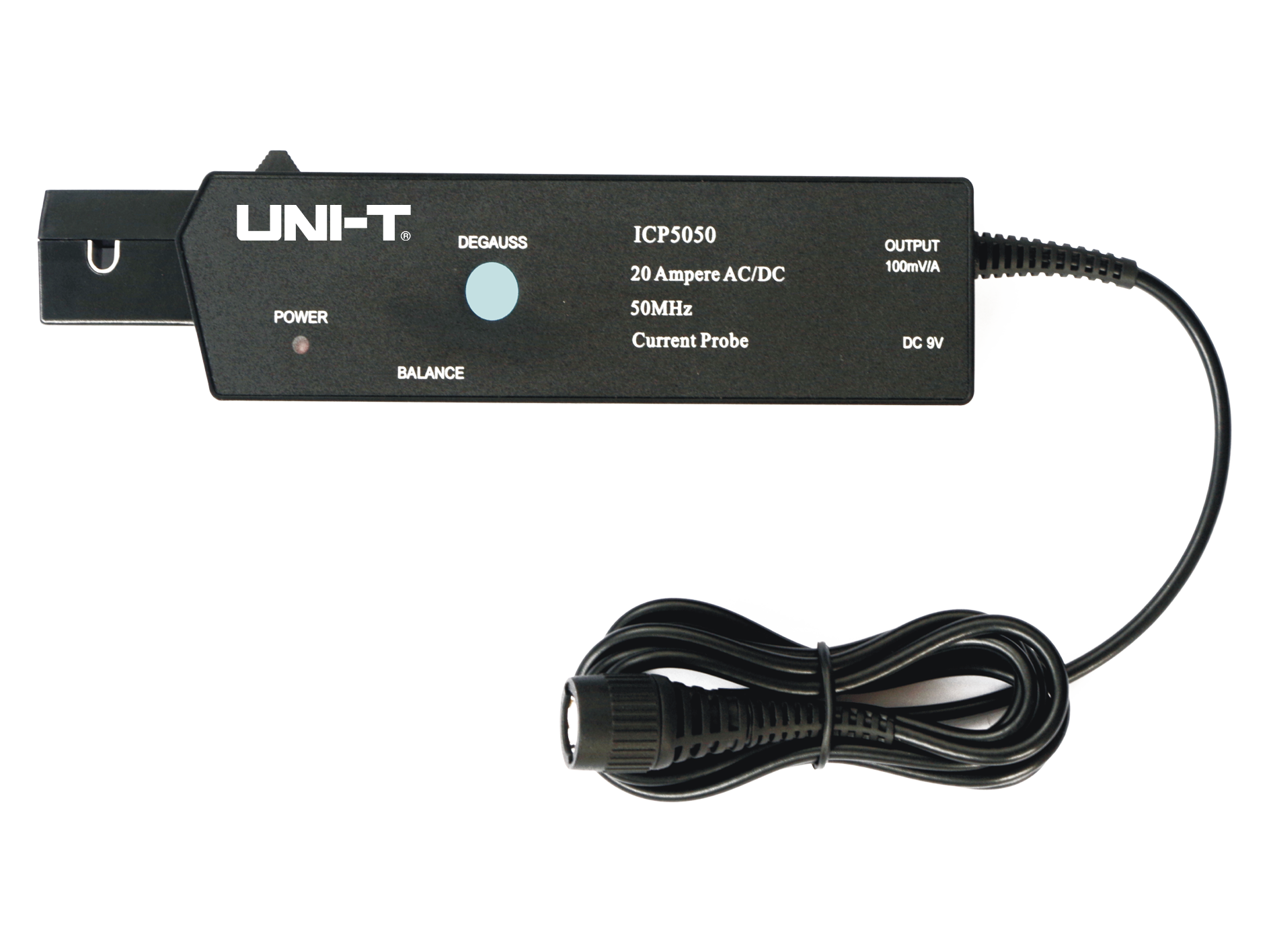
Description:Current range :20A AC/DC, Frequency: DC~25MHz,Conversion ratio:100mV/A
UT-P44
download EN
UT-P44
Description:Current range: 40A AC/DC, Frequency: DC~50MHz,Conversion ratio:50mV/A
UT-P04
download EN
UT-P04
Description:Probe factor:(10:1) Bandwidth: 100MHz.voltage:600Vpp
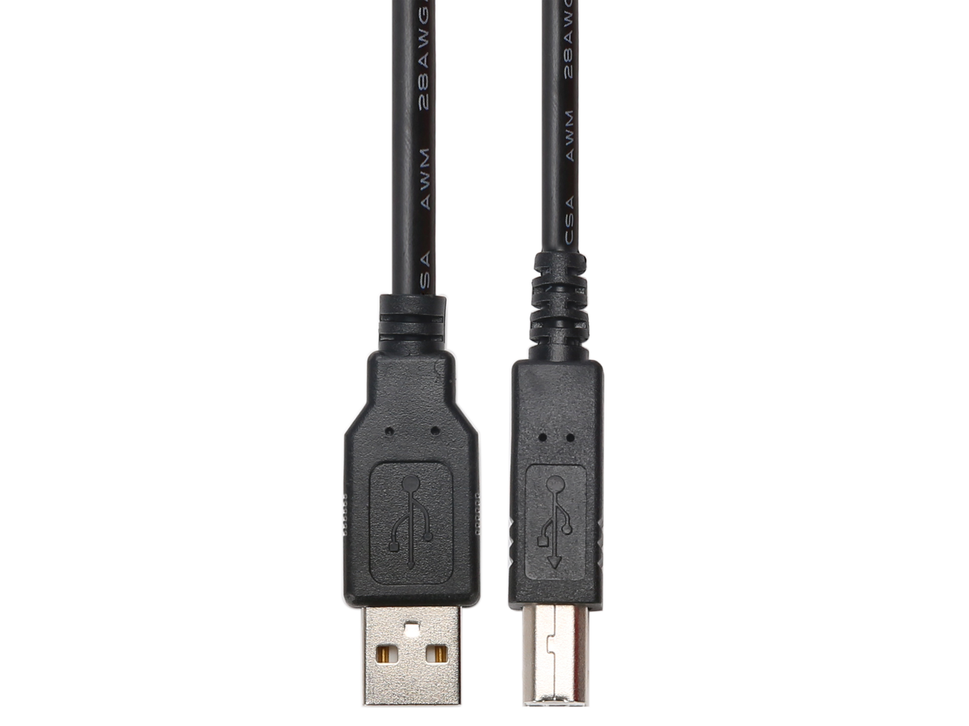
UT-D14
UT-D14
Description:USB 2.0 double-head printing cable:1.5M
UT-L45
UT-L45
Description:BNC-BNC line :1M
UT-P05
download EN
UT-P05
Description:Probe factor:(10:1) Bandwidth: 200MHz.voltage:600Vpp
UT-P03
download EN
UT-P03
Description:Probe factor:(10:1) Bandwidth: 60MHz.voltage:600Vpp
UT-P35
download EN
UT-P35
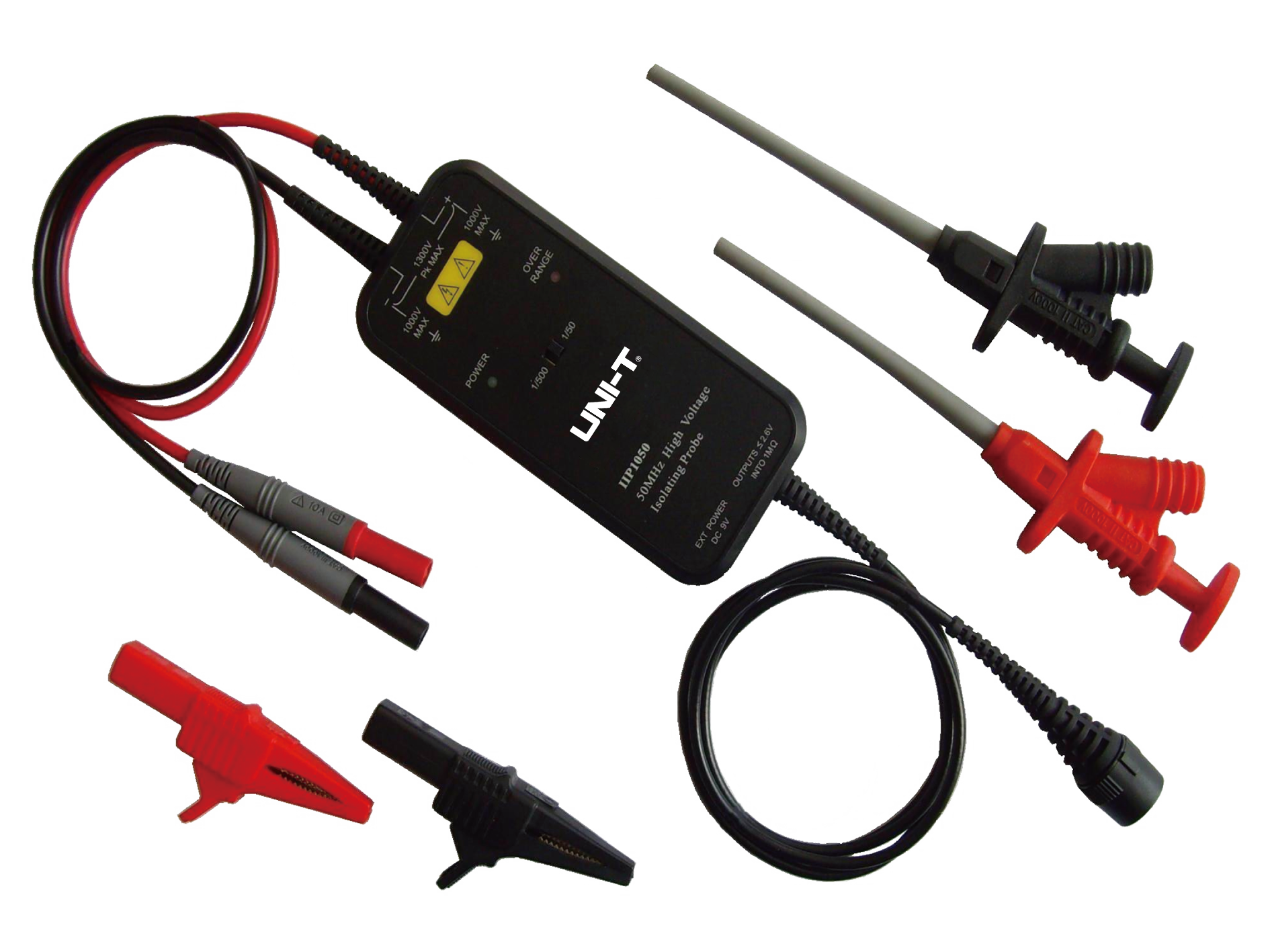
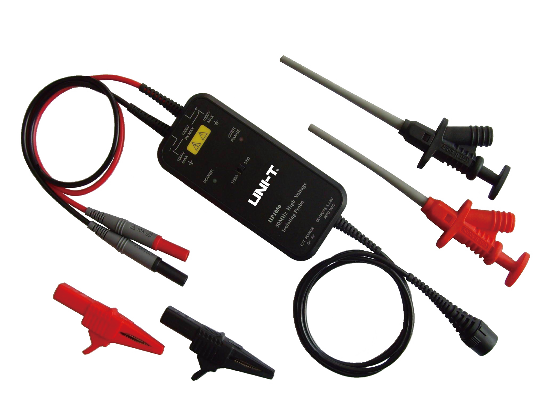
Description:High voltage Differential probe:1:50,130V(DC+peakAC); 1:500,1300V(DC+peakAC),Bandwidth:50MHz,Precision:2%
UT-P36
download EN
UT-P36
Description:High voltage Differential probe: 1/200:560(DC+peakAC) 1/2000:5600(DC+peakAC), Bandwidth:100MHz,Precision:2%
UT-P4100A
download EN
UT-P4100A
Description:100A/600kHz Low frequency current probe Range:100A/10A Freq range:DC~600kHz Rise time:≤583ns
UT-P4030D
download EN
UT-P4030D
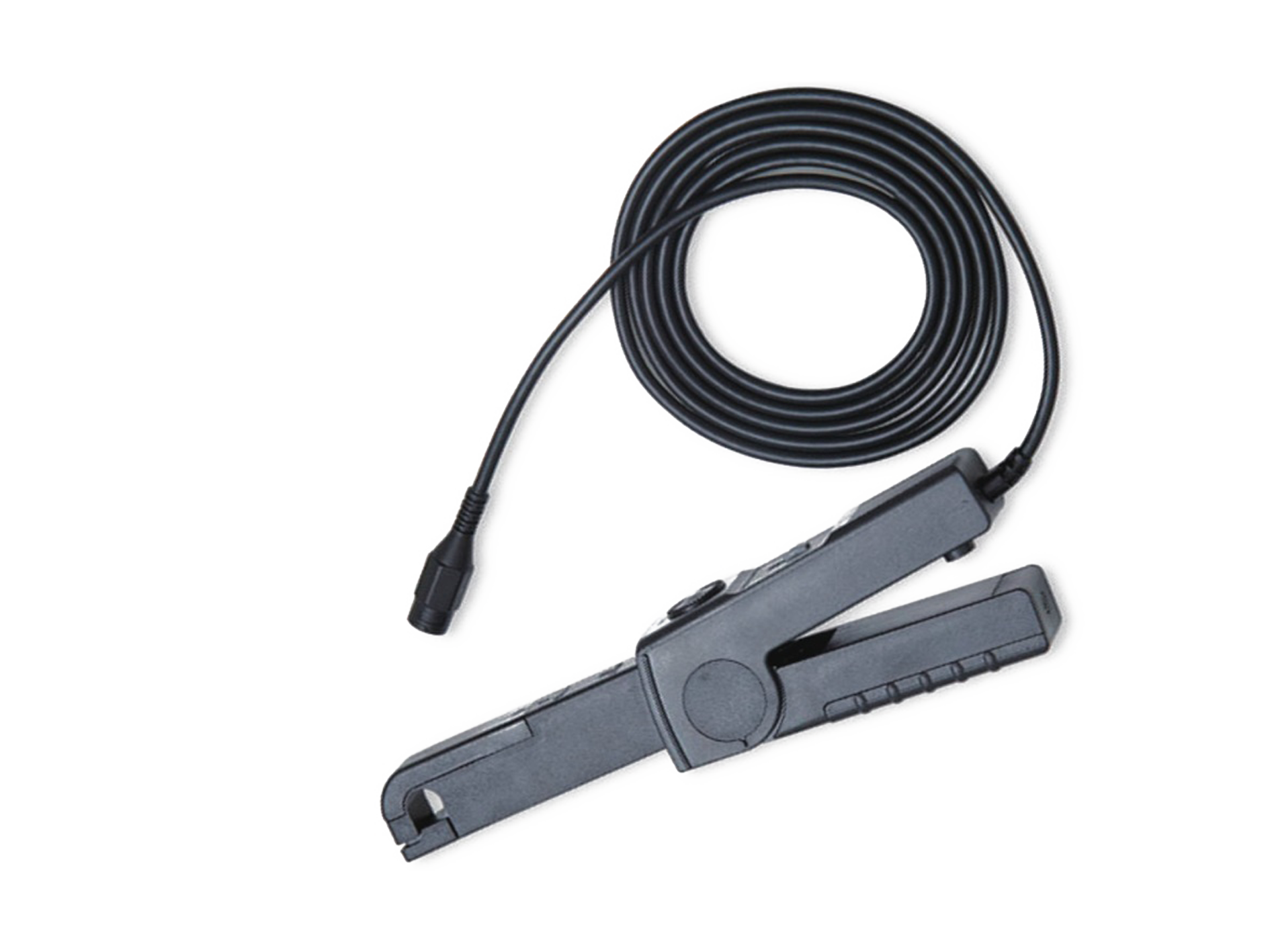
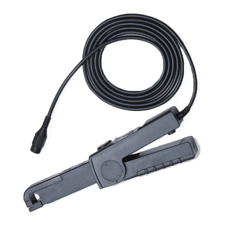
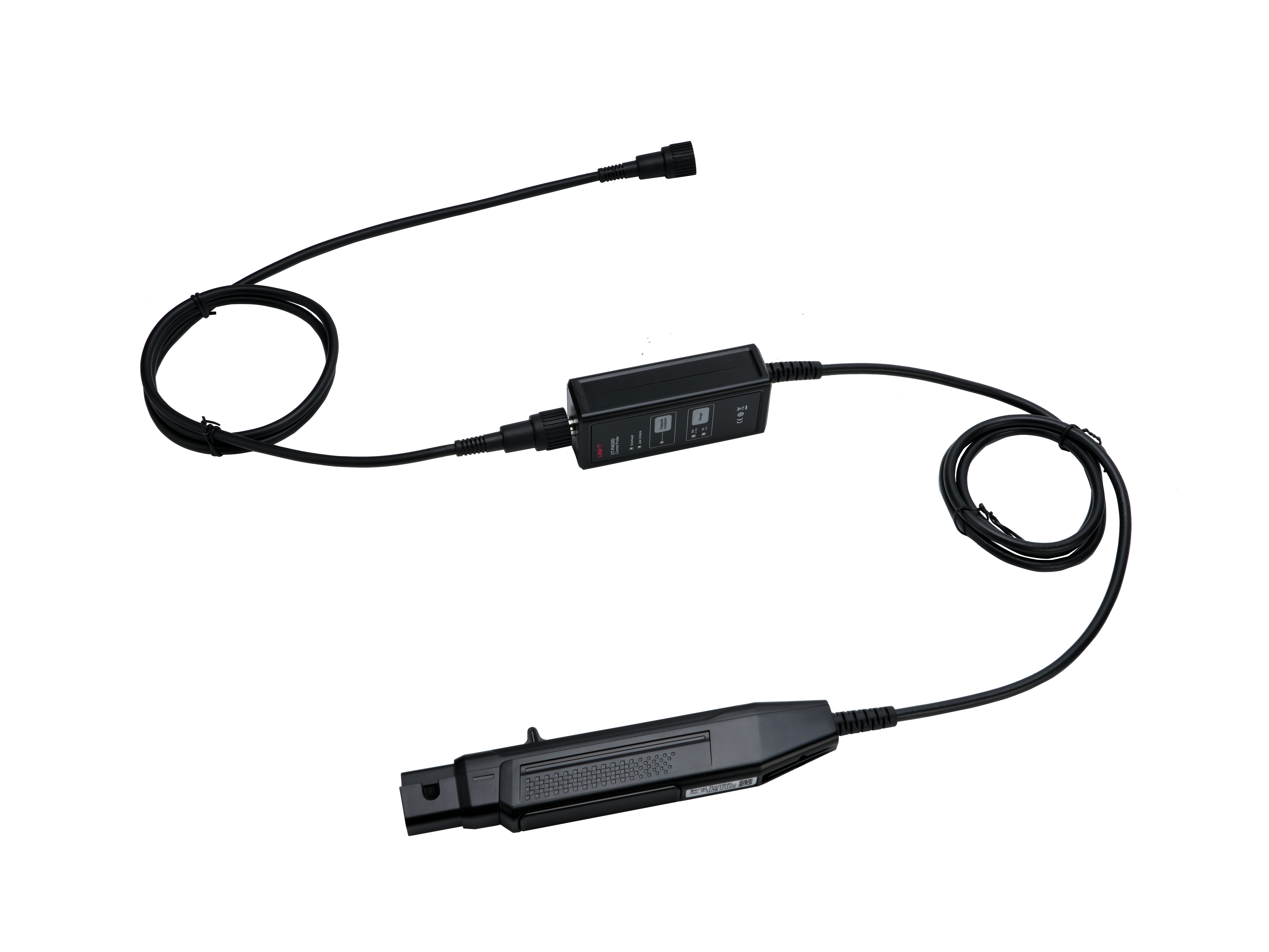
Description:30A/ DC~100MHz High frequency current probe Range:30A/5A Freq range:DC~100MHz Rise time:≤3.5ns
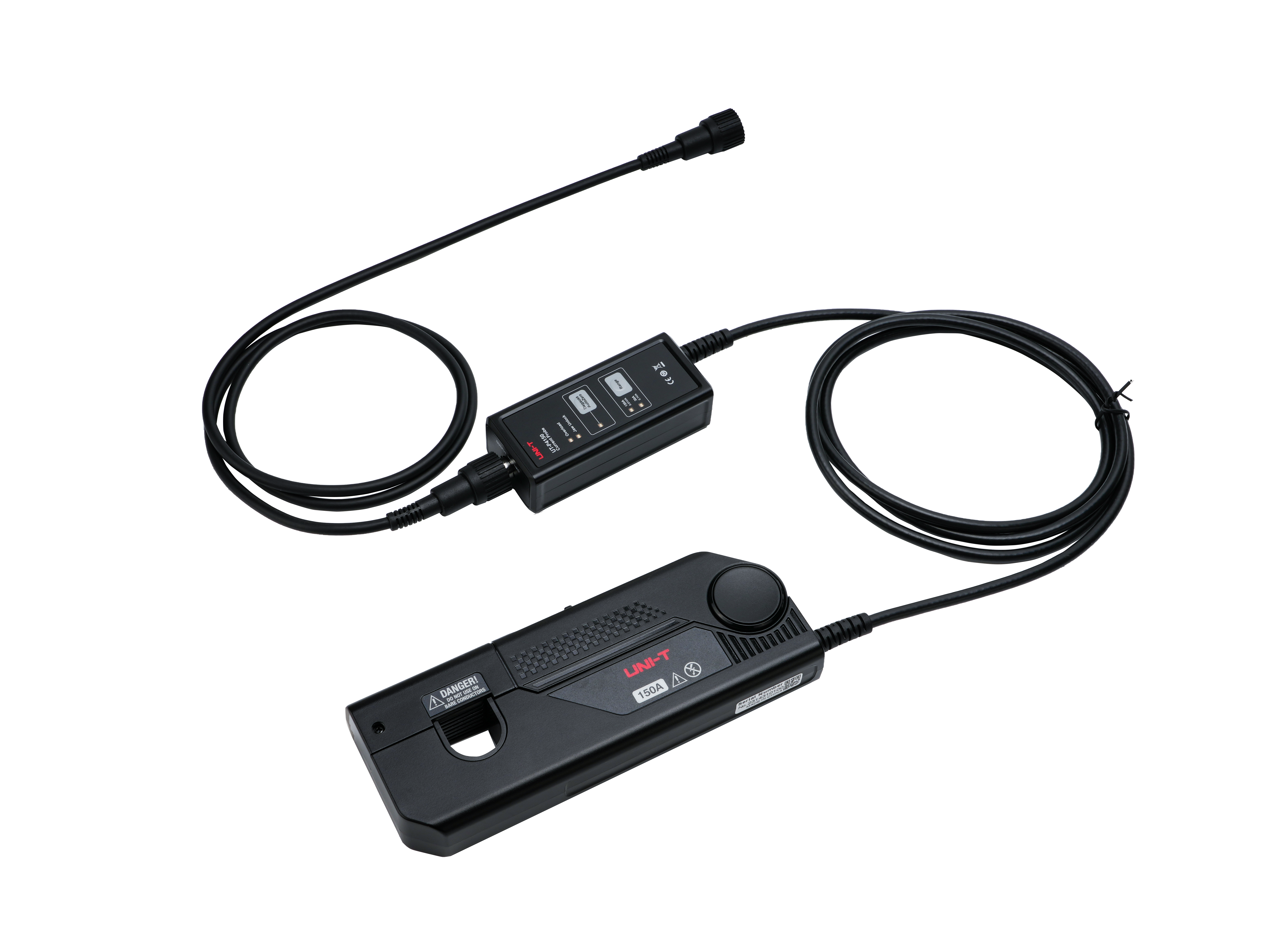
UT-P4150
download EN
UT-P4150
Description:150A/ DC-12MHz High frequency current probe Range:150A/30A Freq range:DC~12MHz Rise time:≤29ns
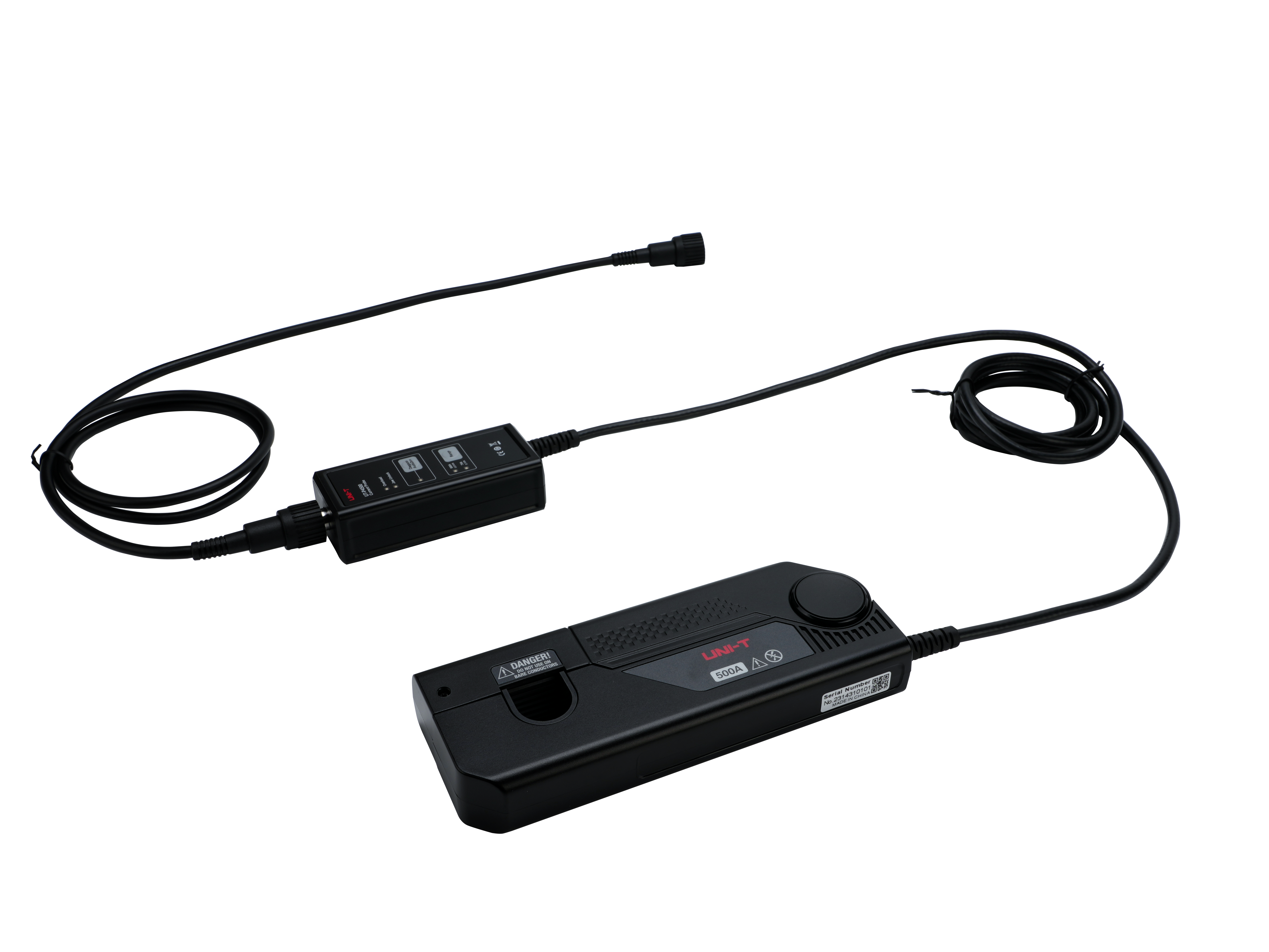
UT-P4500
download EN
UT-P4500
Description:500A/ DC~5MHz High frequency current probe Range:500A/75A Freq range:DC~5MHz Rise time:≤70ns
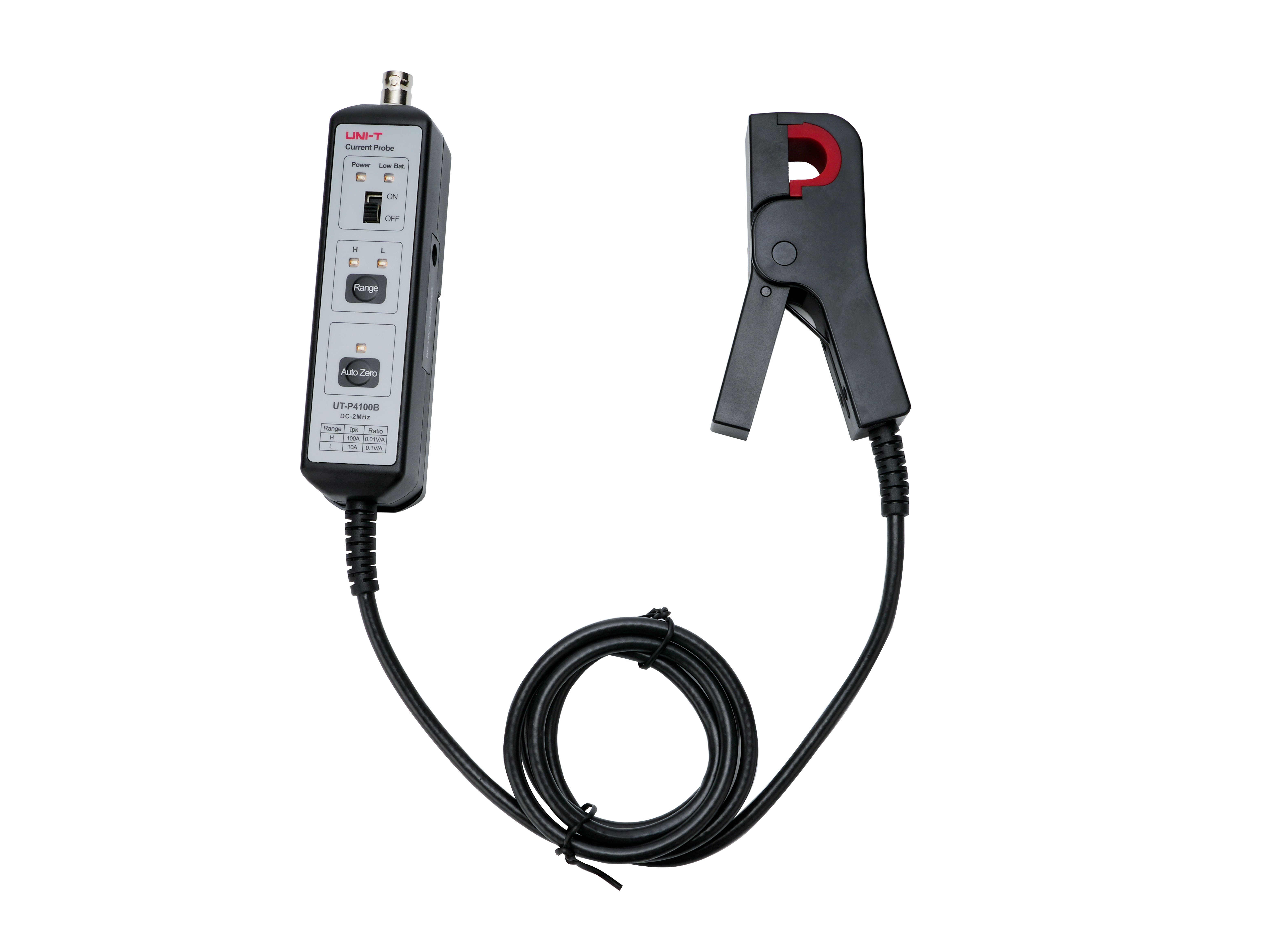
UT-P4100B
download EN
UT-P4100B
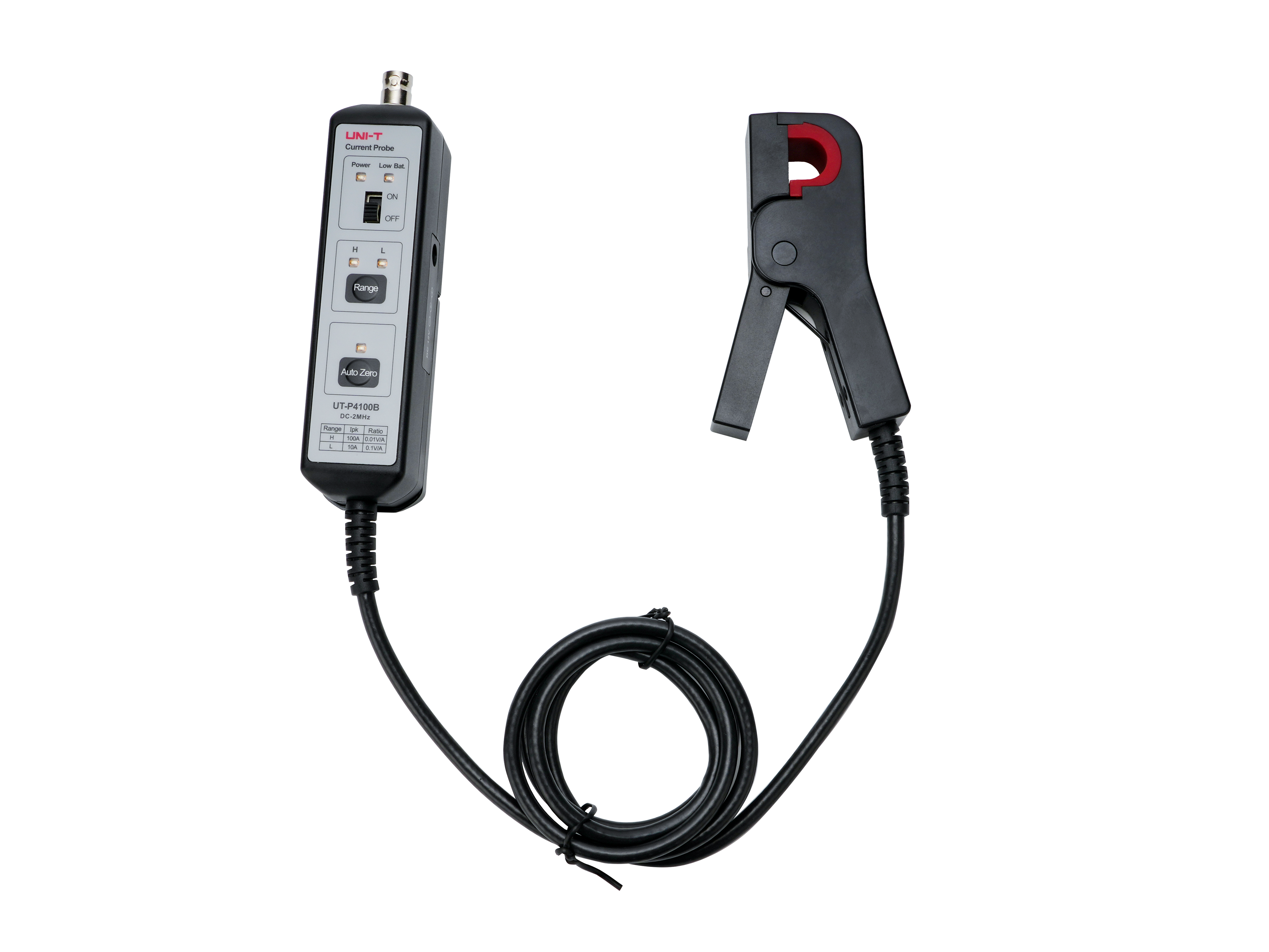
Description:100A/2MHz Low frequency current probe Range:100A/10A Freq range:DC~2MHz Rise time:≤175ns
SOFTWARE
Device Manager
Version: V2.6
2024/8/8
Release notes
FIRMWARE
Video
FAQs
Why the value measured by the oscilloscope is different from the value measured by the multimeter?
How does an oscilloscope measure power supply ripple?
The measurement error of oscilloscope is relatively large
Maintenace and Cleaning
Why is there no waveform output from the signal generator?
No screen display(blank screen)
What is the difference of real-time sampling and equivalent sampling?
What impact does a low sampling rate have on testing and measurement?
The conversion relationship between peak value(Vp), peak-to-peak value(Vpp), and RMS value(Vrms).
What is the relation of channel coupling and trigger coupling?
Why is there a significant difference in RMS voltage measurements when using the same high-voltage probe EN-48000 with a UNI-T oscilloscope compared to an Agilent oscilloscope?
In an oscilloscope, how should we understand the term ±(3% x reading+0.05div)? What does one sampling interval mean?
While measuring a signal, what is the difference between using a probe in 1x mode and 10x mode?
How to use oscilloscope to capture occasional signal?
What is the trigger of oscilloscope?
Why choose an oscilloscope with high waveform capture rate?
What are the differences between the auto, normal, and single trigger modes?
UNI-T oscilloscope has wave record function, how long can it record?
Why is there significant waveform distortion when observing high-frequency signals?
How to solve the issue of having a waveform but unable to display it stably?
What is the trigger of oscilloscope?
What is the trigger hold off?
Why the precision is different from the standard specification?
How to use digital oscilloscope to measure radiate of switching power supply?
How to measure small signals using a digital oscilloscope? For example, small signals from an audio amplifier or power supply ripple noise.
How to measure differential signal using digital oscilloscope ?
What is Rise Time?
What is the difference of analog oscilloscope and digital oscilloscope?
Why does a 1kHz square wave measurement result in ghosting phenomenon?
Why does the instrument display normally when connected to the PC software, but none of the buttons respond?
Why is the phase difference displayed incorrectly when measuring signals with a phase difference of 180 degrees or other phase differences?
Why does a square wave signal appear as a triangle wave when measured?
Why does a square wave signal appear as a sine wave when measured?
Why does the AUTO function sometimes prompt an AUTO failure?
Is the bandwidth of oscilloscope the higher the better?
How to capture continuous waveforms of a signal over a period of time?
Release notes